In this project, we will build a remote-controlled Arduino Air-Boat that can be controlled wirelessly using the 433 MHz RF Radio Modules. We will control this boat using a homemade remote control by building our own 433 MHz transmitter and a receiver module. In the case of remote-controlled devices or communication between two devices, we have a lot of options like IR, Bluetooth, internet, RF, etc. When compared to IR communication, radio communications have some advantages, such as a longer range, and it doesn’t require a line of sight connection between the transmitter and receiver. Also, these modules can communicate in two ways of communication, meaning they can transmit and receive at the same time. So, using this 433MHz RF module, let’s build an Arduino RC Boat in this tutorial. We have developed a wide range of Arduino projects with easy-to-follow instructions, accurate circuit designs, and practical real-world applications.
We have previously built many remote-controlled projects using these 433Mhz RF modules for either controlling a Robot like this RF controlled Robot or for Home Automation applications to Control Home appliances using RF. Apart from using RF modules, we have also built a Bluetooth Controlled Raspberry Pi Car and a DTMF Mobile phone controlled Arduino Robot previously. You can also check out these projects if you are interested.
Components Required for Arduino RC Boat
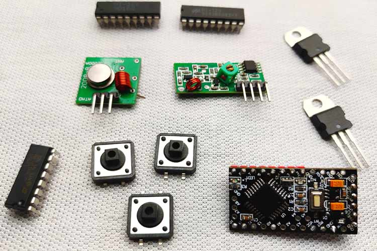
- 433MHz transmitter and receiver
- Arduino (any Arduino, to reduce the size, I am using promini)
- HT12E and HT12D
- Push buttons- 4Nos
- Resistors- 1mega ohm, 47k ohm
- L293D Motor Driver
- 9V Battery (I am using a 7.4-volt battery)- 2Nos
- 7805 regulator- 2Nos
- DC motors- 2Nos
- Motor leaf or propellors(I am using homemade propellors)- 2Nos
- .1uf capacitor- 2Nos
- Common PCB
433MHz RF Transmitter and Receiver Modules
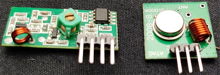
These types of RF modules are very popular among makers. Because of their low cost and simplicity in connections. These modules are best for all forms of short-range communication projects. These modules are ASK (Amplitude Shift Keying) type RF modules. Amplitude-shift keying (ASK) is a form of amplitude modulation that represents digital data as variations in the amplitude of a carrier wave. In an ASK system, the binary symbol 1 is represented by transmitting a fixed-amplitude carrier wave and a fixed frequency for a bit duration of T seconds. If the signal value is 1, then the carrier signal will be transmitted; otherwise, a signal value of 0 will be transmitted. That means they usually draw no power when transmitting Logic “zero”. This low power consumption makes them very useful in battery-operated projects.
433MHZ RF Transmitter
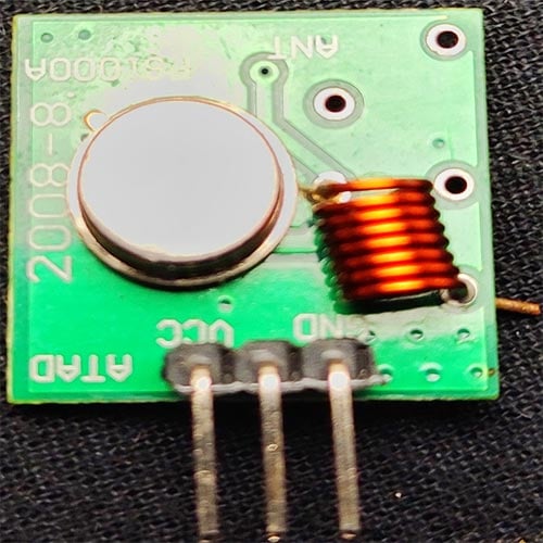
This type of module is super tiny and comes with 3 pins: VCC, ground, and data. Some other modules come with an extra antenna pin. The working voltage of the transmitter module is 3V-12V, and this module doesn't have any adjustable components. One of the major advantages of this module is the low current consumption; it requires almost zero current to send bit zero.
Block Diagram of Arduino RC Boat Transmitter
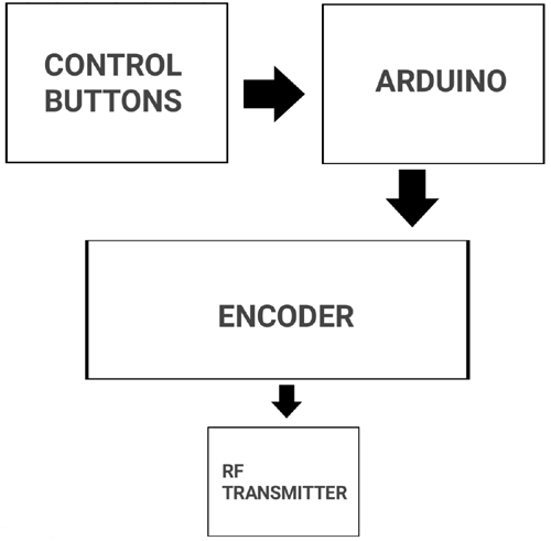
In the above block diagram, there are four pushbuttons (Control Buttons), which are for controlling the direction of the boat. We have four of them for forward, backwards, left, and right. From the pushbuttons, we get logic for controlling the boat, but we can’t directly connect to the encoder; that's why we used the Arduino. You might think why I used Arduino here, it is simply because we need to pull down two parallel data inputs of the encoder at the same time for a backward and forward movement that can’t be achieved with just pushbuttons. Then the encoder encodes the incoming parallel data to serial outputs. Then we can transmit that serial data with the help of an RF transmitter.
Circuit Diagram of the Arduino RC Remote (Transmitter)

In the above circuit, you can see one side of all four pushbuttons connected to four digital pins of Arduino (D6-D9) and all four other sides connected to the ground. That is when we press the button, the corresponding digital pins get a logic low. The four parallel inputs of the HT12E encoder are connected to four digital pins of Arduino (D2-D5). So with the help of Arduino, we can decide the input of the encoder.
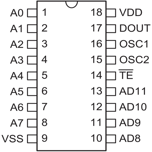
And talking about the encoder HT12E is a 12-bit encoder and a parallel input-serial output encoder. Out of 12 bits, 8-bits are address bits that can be utilized for controlling multiple receivers. The pins A0-A7 are the address input pins. In this project, we are controlling only one receiver, so we don't want to change its address. I connected all address pins to the ground. If you want to control different receivers with one transmitter, you can use dip switches here. AD8-AD11 are the control bit inputs. These inputs will control the D0-D3 outputs of the HT12D decoder. We need to connect an oscillator for the communication, and the oscillator frequency should be 3KHz for 5V operation. Then the resistor value will be 1.1MΩ for 5V. Then I connected the output of the HT12E to the transmitter module. We already mentioned that the Arduino and rf transmitter module both of these devices work on 5V high voltage, which will kill them, so to avoid this, I added the 7805, a voltage regulator. Now we can connect (Vcc) 6-12volt any type to the input.
Building the RC BOAT Transmitter Circuit
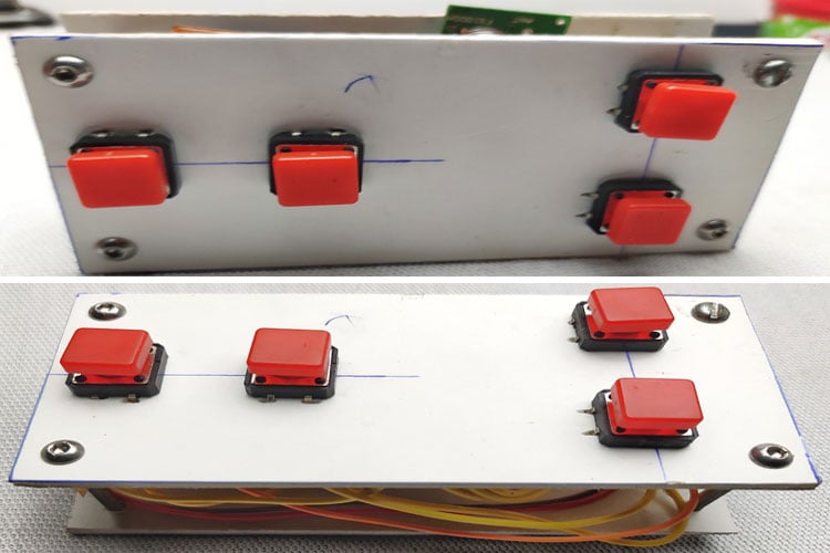
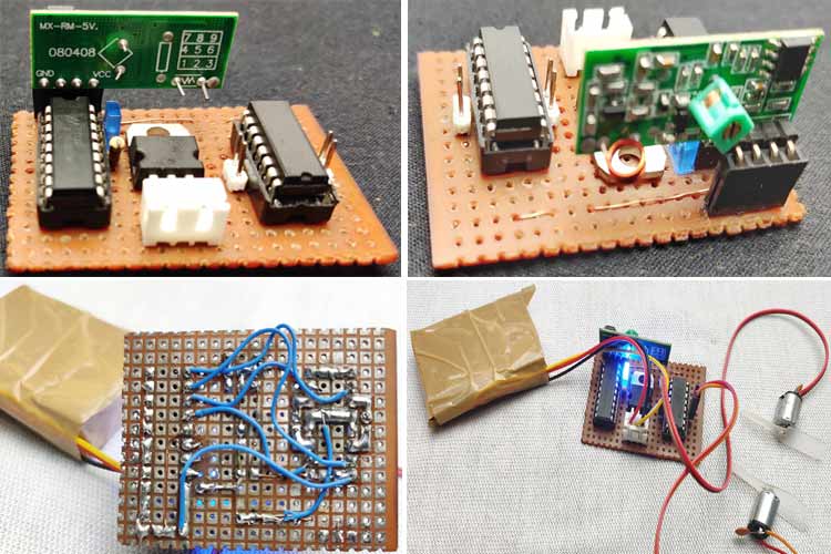
I soldered every component on a common PCB. Remember, we are working on an RF project, so there are a lot of chances for different types of interference, so connect all components as closely as possible. It's better to use female pin headers for Arduino and the transmitter module. Also, try to solder everything on the copper pads instead of using extra wires. Finally, connect a small wire to the transmitter module that will help to increase the total range. Before connecting the Arduino and transmitter module, double-check the voltage of the lm7805 output.
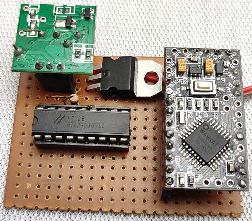
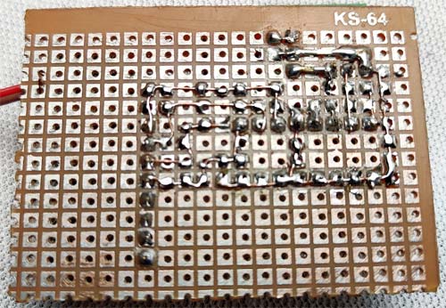
The above image shows the top view of the completed RC Boat transmitter circuit, and the Bottom view of the completed RC Boat Transmitter circuit is shown below.
Building the Arduino RC Boat Transmitter Enclosure
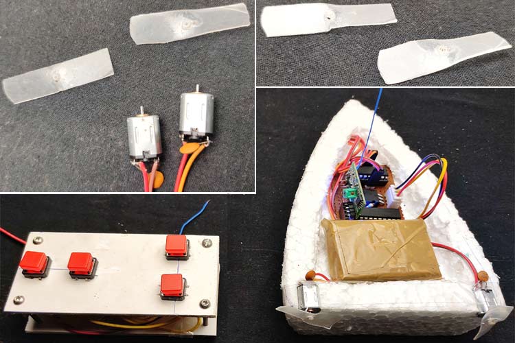
A decent body is necessary for the remote. This step is all about your ideas; you can create a remote body with your ideas. I am explaining how I made this. For making a remote body, I chose 4mm MDF sheets. You can also choose plywood, foam sheet, or cardboard. I cut two pieces from that with a length of 10cm and a breadth of 5cm. Then I marked the positions for the buttons. I placed the direction buttons on the left side and the forward and backward buttons on the right. On the other side of the sheet, I connected the push buttons to the main transmitting circuit. Remember, a normal pushbutton has 4 pins that are two pins for each side. Connect one pin to the Arduino and the other pin to the ground. If you are confused about that, please check it with a multimeter or check the datasheet.
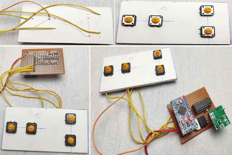
After connecting all these things, I placed the control circuit in between the two MDF boards and tightened it with some long bolts (please refer to the images if you want). Once again, creating a good body is all about your ideas.
433Mhz Receiver Module
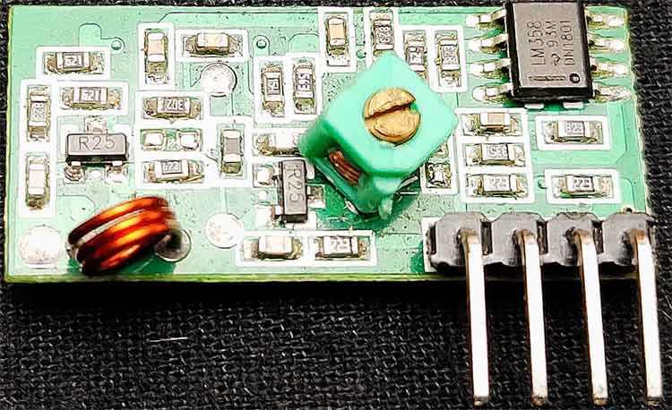
This receiver is also very tiny and comes with 4 pins: VCC, ground, and the two middle pins are data out. The working voltage of this module is 5v. Like the transmitter module, this is also a low-power module. Some modules come with an extra antenna pin, but in my case, that is not present.
Block Diagram of the Arduino RC Boat Receiver
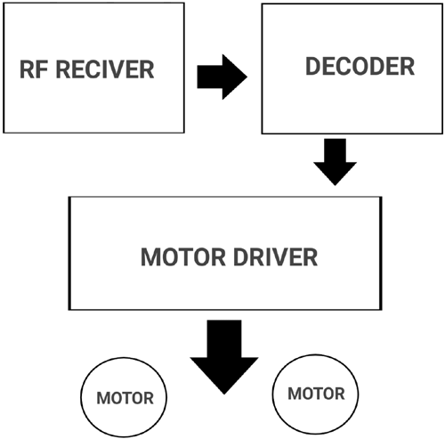
The above block diagram describes the working of the RF receiver circuit. First, we can receive the transmitted signals using the RF receiver module. The output of this receiver is serial data. But we can't control anything with this serial data; that's why we connected the output to the decoder. The decoder decodes the serial data into our original parallel data. In this section, we don't require any microcontrollers; we can directly connect the outputs to the motor driver.
Circuit Diagram of Arduino RC Boat Receiver

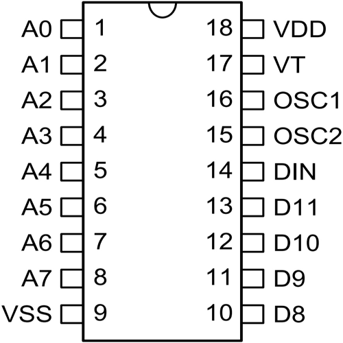
The HT12D is a 12-bit decoder, which is a serial input-parallel output decoder. The input pin of the HT12D will be connected to a receiver that has a serial output. Among the 12 bits, 8 bits (A0-A7) are address bits, and the HT12D will decode the input if only it matches its current address. D8-D11 are the output bits. To match this circuit to the transmitter circuit, I connected all the address pins to the ground. Data out of the module is the serial type, and the decoder decodes this serial data to original parallel data, and we get it out through D8-D11. To match the oscillation frequency should connect the 33-56k resistor to the oscillator pins. Led on the 17th pin indicates a valid transmission; it only lights after the receiver is connected to a transmitter. The voltage input of the receiver is also 6-12 volts.
To control motors, I used the L293D IC. I chose this IC because it decreases the size and weight, and this IC is best for controlling two motors in two directions. L293D has 16 pins; the diagram below shows the pinouts.
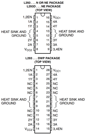
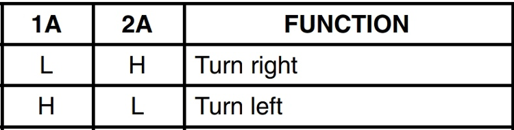
1, 9 pins are the enable pin, we connect that to 5 v to enable motors 1A, 2A, 3A, and 4A are the control pins. The motor will turn to the right if the pin 1A goes low and 2A goes high, and the motor will turn to the left if 1A goes low and 2A high. So we connected these pins to the output ps of the decoder. 1Y, 2Y, 3Y, and 4Y are the motor connection pins. Vcc2 is the motor driving voltage pin, if you are using a high voltage motor, then you connect this pin to the corresponding voltage source.
Building the Receiver Circuit of Arduino RC Boat
Before building the receiver circuit, you should remember some important things. The important one is the size and weight because after building the circuit, we need to fix it on the boat. So if the weight increases, that will affect the buoyancy and movement.
So same as in the transmitter circuit, solder every component in a small common PCB and try to use minimum wires. I connected pin 8 of the motor driver to 5v because I am using 5V motors.
Building the RC-BOAT
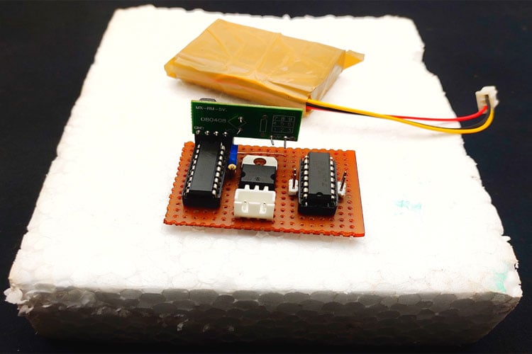
I tried different materials to build the boat body. And I got a better result with thermocol sheet. So I decided to build the body with thermocol. First, I took a 3cm thick thermocol piece and place the receiver circuit on top, then I marked the shape of the boat in thermocol and cut. So this is my way to build the boat, you can build according to your ideas.
Motors and Propellers for Arduino Air Boat
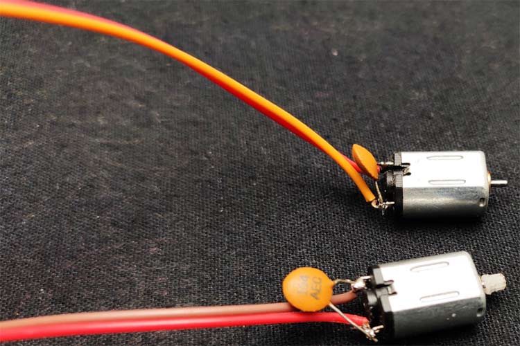
Once again weight matters. So choosing the correct motor is important, I choose 5volt, n20 type normal dc motors which is small and weightless. To avoid the RF interferences should connect 0.1uf capacitor parallel to motor inputs.
In the case of propellers, I made propellers using plastic sheets. You can buy propellers from the store or you can build your own both will work just fine. To build the propellers, first, I took a small plastic sheet and cut two small pieces from it and I bend the pieces with the help of candle heat. Finally, I put a small hole in its center for the motor and fixed to the motor that's it.
Working of Arduino RC Boat
This boat has two motors lets call it left and right. If the motor moves to clockwise also (the position of the propellor also depends) propellor sucks air from the front and exhaust to the backside. That generates forward drag.
Forward movement: If both the left and right motors rotate to clockwise that will forward movement
Backward movement: If both the left and right motors to rotate counterclockwise(that is propeller sucks air from the backside and exhaust to the front side )that will make backward movement
Left movement: If only the right motor rotates that is boat get only drag from the right side that will the boat to move to the left side
Right movement: If only the left motor rotates that is boat gets only drag from the left side that will make the boat move to the right side.
We connected the motors driver's input to four output bits of the decoder(D8-D11). we can control these 4 outputs by connecting the AD8-AD11 to the ground that is the buttons in the remote. For example, if we connect AD8 to the ground that will activate the D8. So such a way we can control the two motors in two directions using these 4 outputs. But we can't control two motors by just one button (we need that for forward and backward movement) that's why we used the Arduino. With help of Arduino, we can select the input data pins as our wish.
Arduino Programming of the RC Boat
The programming of this boat is very simple because we want only some logic switching. And we can achieve everything with basic Arduino functions. The complete program for this project can be found at the bottom of this page. The explanation of your program is as follows
We start the program by defining the integers for four input buttons and decoder inputs pins.
int f_button = 9;
int b_button = 8;
int l_button = 7;
int r_button = 6;
int m1=2;
int m2=3;
int m3=4;
int m4=5;
In the setup section, I defined the pin modes. That is, the buttons are connected to digital pins so these pins should define as input and we need to get output for the input of the decoder so we should define those pins as output.
   pinMode(f_button,INPUT_PULLUP);
  pinMode(b_button,INPUT_PULLUP);
  pinMode(l_button,INPUT_PULLUP);
  pinMode(r_button,INPUT_PULLUP);
  pinMode(m1,OUTPUT);
  pinMode(m2,OUTPUT);
  pinMode(m3,OUTPUT);
  pinMode(m4,OUTPUT);
Next in the main loop function, we will read the button status using the digitalread function of Arduino. If the pin status goes low that means the corresponding pin is pressed then we will execute the conditions as like follows-
if ( digitalRead(f_button)==LOW)
That means the forward button is pressed
 {
   digitalWrite(m1, LOW);
   digitalWrite(m3, LOW);
   digitalWrite(m2, HIGH);
   digitalWrite(m4, HIGH);
 }
This will pulldown m1 and m2 of the encoder this will activate both motors on the receiver side. Similarly, for backward movement
 {
   digitalWrite(m1, HIGH);
   digitalWrite(m3, HIGH);
   digitalWrite(m2, LOW);
   digitalWrite(m4, LOW);
 }
For left movement
 {
   digitalWrite(m1, LOW);
   digitalWrite(m3, HIGH);
   digitalWrite(m2, HIGH);
   digitalWrite(m4, HIGH);
 }
For right movement
 {
   digitalWrite(m1, HIGH);
   digitalWrite(m3, LOW);
   digitalWrite(m2, HIGH);
   digitalWrite(m4, HIGH);
 }
After compiling the code, upload it to your Arduino board.
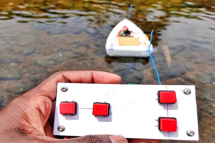
Troubleshooting: Place the boat on the water surface and check whether it is moving correctly if not try to change the polarity of motors and propellers. Also, try to balance weight.
The complete working of the project can be found in the video linked at the bottom of this page. If you have any questions leave them in the comment section.
We have created numerous electronics projects featuring clear instructions, circuit designs, and real-world use cases.
Complete Project Code
int f_button = 9;
int b_button = 8;
int l_button = 7;
int r_button = 6;
int m1 = 2;
int m2 = 3;
int m3 = 4;
int m4 = 5;
void setup () {
  pinMode(f_button, INPUT_PULLUP);
  pinMode(b_button, INPUT_PULLUP);
  pinMode(l_button, INPUT_PULLUP);
  pinMode(r_button, INPUT_PULLUP);
  pinMode(m1, OUTPUT);
  pinMode(m2, OUTPUT);
  pinMode(m3, OUTPUT);
  pinMode(m4, OUTPUT);
}
void loop() {
  if ( digitalRead(f_button) == LOW)
  {
    digitalWrite(m1, LOW);
    digitalWrite(m3, LOW);
    digitalWrite(m2, HIGH );
    digitalWrite(m4, HIGH);
  }
  if ( digitalRead(b_button) == LOW)
  {
    digitalWrite(m2, LOW);
    digitalWrite(m4, LOW);
    digitalWrite(m1, HIGH);
    digitalWrite(m3, HIGH);
  }
  if ( digitalRead(l_button) == LOW)
  {
    digitalWrite(m1, LOW);
    digitalWrite(m2, HIGH);
    digitalWrite(m3, HIGH);
    digitalWrite(m4, HIGH);
  }
  if ( digitalRead(r_button) == LOW)
  {
    digitalWrite(m1, HIGH);
    digitalWrite(m2, LOW);
    digitalWrite(m3, HIGH);
    digitalWrite(m4, HIGH);
  }
}